
- Pablo EA1FID Álvarez

- 16 Sep, 2023
Ponencia en Iberradio 2023
El pasado día 16 de septiembre tuvo lugar la mayor feria de radiocomunicacioens amateur en España: Iberradio. Como parte del programa, tuve la …
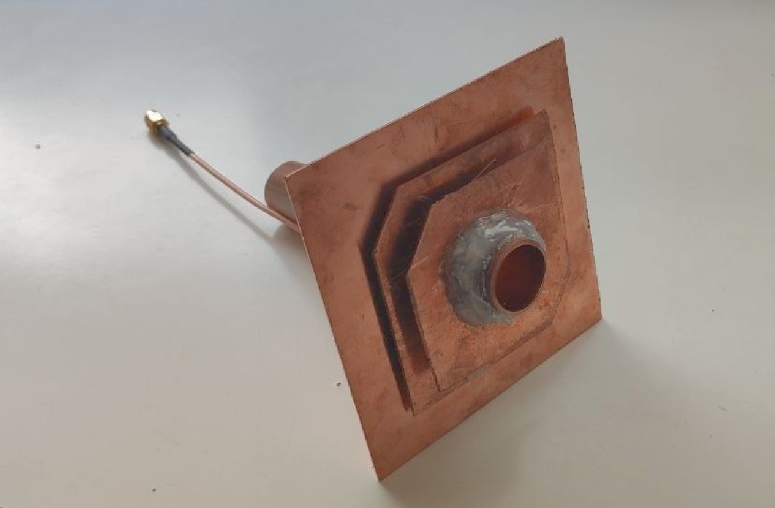
Bubela is a stacked patch antenna characterised by its huge bandwidth and increased gain.
This design started as a solution to a problem that alots of amateur radi operators specialised in microwave bands face every time they want to operate on 2,4GHz: due to the small bandwidth of most antennae designed for the QO-100 satellite, it is mandatory to have different dish feeders depending on whether you want to work the geostationary transponder or make some terrestrial QSOs at the lower part of the band. However, the decision of going for a stack patch instead of for a traditional one, brought some other interesting improvements over most of other commercially available antennae.
This antenna has been designed with the objective of improving some aspects of other antennas from the market while adding new useful features for the radio operator.
Huge bandwidth: as it can be seen in the specifications below, this antenna not only provides a SWR of less than 1.3 accorss the whole 13cm band, that is can also be used as a receiving antenna for part of the 2,4GHz ISM band. No more changing the dish feed depending on whether you are working the QO-100 or making microwave QSOs!
Increased gain: the use of a second patch with a higher substrate height increases the directivity of the feed. This way, we approach even more to the theoretical optimal illumination of the reflector of -12dB at its edges.
Thought to be used with commercial satellite dishes: this design will offer the best performance with parabolic reflectors whose f/D ratio is 0,4 or lower, like the vast majority of commercially available options.
Cheap and easy to build: this antenna can be build at home using easy to find materials and tools. Moreover, the total cost of the materials is less than 25€
Optimal performance: Xurelo-6 covers the whole 6m band with a SWR lower than 1.5, offering good gain and low SLL across the whole band.

| Specification | Value | Units |
|---|---|---|
| Gain | 9.56 | dBi |
| 3 dB Beamwidth (E plane) | 58.9 | º |
| 3 dB Beamwidth (H plane) | 58.0 | º |
| Efficiency | 99.0 | % |
| Impedance | 50 | Ω |
| Lowest SWR | 1.0 | - |
| Bandwidth | 250 | MHz |
| 11 | % | |
| SLL (E plane) | -18.2 | dB |
| SLL (H plane) | -23.1 | dB |
| Polarization | LHCP | - |
| XPD | 15 | dB |
| F/B | 25.21 | dB |
Note: bandwidth is measured between points at 1.5 SWR (very conesrvative measure). XPD is referred to broadside direction
| Simulated radiation pattern | Simulated SWR |
|---|---|
 |  |


| Material | Quantity |
|---|---|
| 100x100 copper sheets (up to 1mm height) | 3 |
| 22mm copper pipe | 1 |
| 50Ohm coaxial cable | 20cm |
| SMA male connector | 1 |
* Other conductive materials can be used intead of copper. However, copper is one of the easiest to solder at home, hence the decision to use it in our prototype.
** Make sure that you choose a coaxial cable whose performance at 2.4GHz is good enought as for not deteriorating the overall performance of the antenna.
All of the measurements, plans, .stl files and more can be found in our GitHub repository
First of all, it is necessary to cut thethree copper sheets in the shape described in the plans. Important: in order to achieve the aforementioned specifications, it is necessary to cut the pieces with the maximum precision and accuracy possible, even submillimetric is that is an option to you. Using a CNC cut machine is highly recommended. Otherwise, the antenna will work fine, but its performance can decrease in some tenths of dB.
Drill a small (approx. 1mm) hole both on the ground plane and on the lower patch corresponding to the feeding point where the coaxial will be soldered.
Draw some marks on the copper tubing corresponding to the pace every sheet will be soldered. Once again, it is crucial to be as precise as possible.
Solder the ground plane and the first patch to the copper tube.
Solder the coax to the corresponding pieces of copper (the shield to the ground plane and the inner conductor to the patch).

Finally, solder the upper patch to the antenna
Enjoy!
Note: if you own a VNA that works up to 3GHz you may want to tune the patch. For this pupose, you can modify a bit (1mm or less) the distance between the different patchesaccross the tube. Nevertheless, due to the high bandwidth of the antenna, this is not a requirement at all (it will work fine without further tuning).

Written By
Quantum Engineer by the Eidgenössische Technische Hochschule Zürich (ETH), Telecommunications Engineer by the Universidad Politécnica de Madrid (UPM) and Amateur Radio operator (callsign EA1FID) from a young age.

El pasado día 16 de septiembre tuvo lugar la mayor feria de radiocomunicacioens amateur en España: Iberradio. Como parte del programa, tuve la …
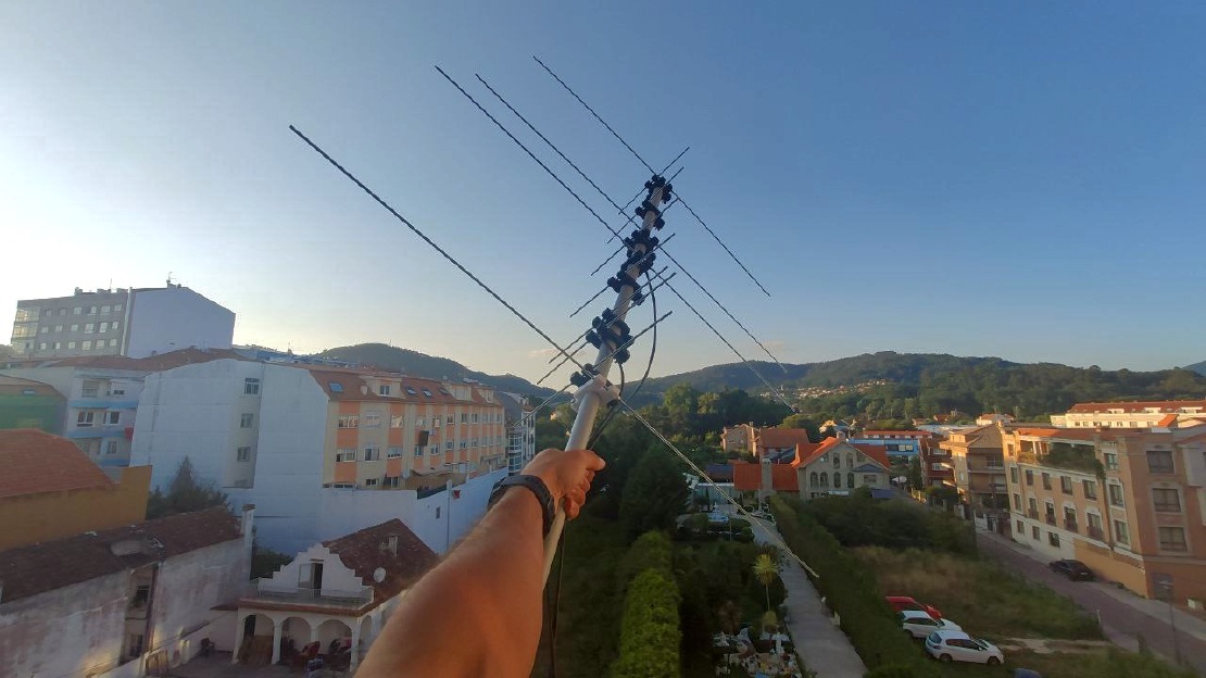
Today, we are glad to present you a very special antenna: Aiga. Aiga is a double band VHF/UHF antenna designed for portable use. In this way, it uses …