
- Pablo EA1FID Álvarez

- 16 Sep, 2023
Ponencia en Iberradio 2023
El pasado día 16 de septiembre tuvo lugar la mayor feria de radiocomunicacioens amateur en España: Iberradio. Como parte del programa, tuve la …
Thanks to the experience obtaing thought the different design stages of Raposo-2, we are glad to annouce the new member to the family: Raposo-70.
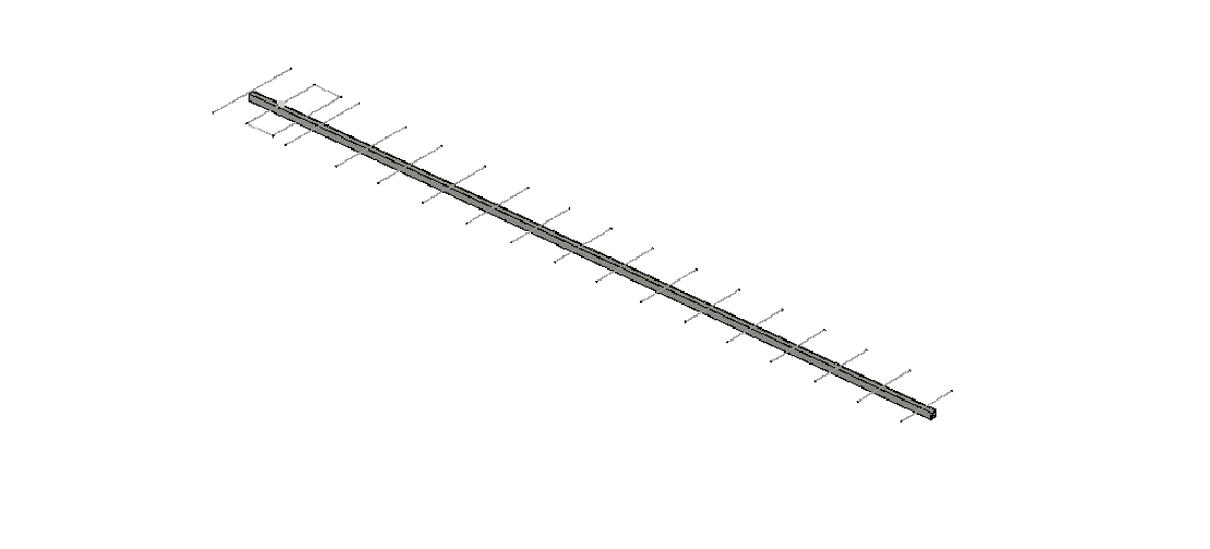
Raposo-70 is a LFA low-noise and high-gain yagi for the 70cm band. It features a compact design but optimised specs for DXing.
Raposo-70 shares most of the fatures of its predecessor, Raposo-2:
Low noise: its reduced SLL results in lower received noise, specially when pointing to higher elevations (satellites, EME and MS)
Optimised for Amatur Radio: Raposo-2 is the ideal antenna for Amateur Radio, since it has been designed specifically for its use at long range radio communications
Different materials: it is possible to buils this antenna by using either non-conductive or conductive booms, thanks to the 3D printable supports from our GitHub repository. Besides, you can choose the diameter of the elements beween M3 and M6 metrics according to your needs

| Specification | Value | Units |
|---|---|---|
| Gain | 14.04 | dBi |
| 3 dB Beamwidth (E plane) | 38.7 | º |
| 3 dB Beamwidth (H plane) | 42.9 | º |
| Efficiency | 99.7 | % |
| Impedance | 50 | Ω |
| Lowest SWR | 1.05 | - |
| Bandwidth | 3.3 | MHz |
| 0.9 | % | |
| SLL (E plane) | -22.5 | dB |
| SLL (H plane) | -18.8 | dB |
| Polarization | Linear | - |
| XPD | >60 | dB |
| F/B | 30.35 | dB |
Note: bandwidth is measured between points at 1.5 SWR (very conesrvative measure). XPD is referred to broadside direction
| Simulated radiation pattern | Simulated SWR |
|---|---|
 |  |

All of the measurements, plans, .stl files and more can be found in our GitHub repository
For this antenna, we will not provide any specific build instruction. This is because they can vary a lot depending on the materials you decide to use and the specific application you want to use this antenna for. Nevertheless, here are some general guidelines or advices for achiving its full potential:
Note that this antenna is designed for achieving optimal performance in a specific portion of the 70cm band. Tune ir accordingly.
Non-conductive fiberglass boom is recommended. However, Raposo-2 and Raposo-2 Mini can be build by using a conductive boom separed at least 5mm from the antenna elements. You can find several 3D-printable element supports in our repository, and choose the one that fits your needs the best.
Use white ABS/PETG with enought infill if you are going to use this antenna for extended periods of time in places with high temperatures.
The optimal diameter of the elements is either M3 or M4. A higher diameter may deform the radiation pattern and increase the overall weight of the antenna.
The use of a balun or RF choke is recommended. Use either some ferrite cores at the end of the coaxial cable or a suitable 1:1 balun/transformer.
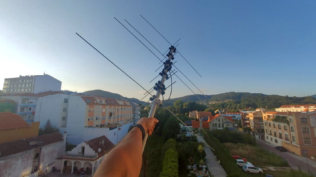
It is recommended to place this antenna at least 1m above ground.
It is possible to stack more than one Raposo-2 in order to build an antenna array. Optimal stacking distance in order to achieve increased gain without generating large grating lobes is between 0.8 and 1m for horizontal stacking and 0.8to 0.95 for vertical stacking.
The use of a vertical metal tubing perpendicular to the elements as antenna support does not affect the overall performance of Raposo-70.


Written By
Quantum Engineer by the Eidgenössische Technische Hochschule Zürich (ETH), Telecommunications Engineer by the Universidad Politécnica de Madrid (UPM) and Amateur Radio operator (callsign EA1FID) from a young age.

El pasado día 16 de septiembre tuvo lugar la mayor feria de radiocomunicacioens amateur en España: Iberradio. Como parte del programa, tuve la …
Today, we are glad to present you a very special antenna: Aiga. Aiga is a double band VHF/UHF antenna designed for portable use. In this way, it uses …